Fundamentals of TTL Strobe Control by Pavel Kolpakov
How has TTL flash changed since the beginning of the digital era?
In digital cameras, the technology of reflection from a light-sensitive surface was inapplicable due to the low reflectivity of light-sensitive semiconductor matrices. Therefore, with the advent of digital cameras, the idea of a TTL flash has fundamentally changed. Modern digital TTL flash for DSLR cameras works as follows:
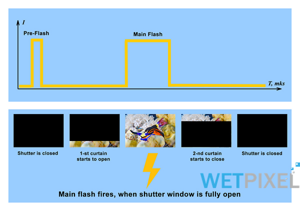
- When the shutter button is pressed (or the AE-lock button), the flash unit emits a low-intensity preflash preceding the mirror opening at the camera’s command.
- The camera performs TTL metering of the light reflected from the object of this preflash with its built-in TTL exposure meter. As the mirror has yet to be raised, nothing prevents TTL metering in a classical way, as when measuring the illumination of an object with natural light.
- Based on the information received about the bounced preflash and taking into account the camera settings (ISO, effective aperture of the lens, aperture, shutter speed, focusing distance, etc.), the camera calculates the required duration of the main flash for correct illumination of the subject in the frame, then transmits it digitally via the hot shoe interface to the external flash
- The mirror rises, the shutter window opens. The flash unit emits the powerful main flash of the calculated duration at the appropriate command from the camera. Note that this flash is emitted when the shutter window is fully open, exposing the entire image at once. Then the shutter closes.
Thus, by changing the duration of the main flash based on this analysis of preflashes, the camera adjusts the flash exposure of the subject in the frame. This explains how TTL works with a conventional monolithic flash pulse. Let me remind you that most of the classic underwater flashes only use this type of flash and only support this type of TTL. The actual kind of flash is relevant at shutter speeds no faster than the “X-sync” shutter speed. For example, at shutter speeds at which the shutter, during the movement of its parts, physically has a particular moment of the complete opening of the window, so that at this moment it is possible to expose the image as one whole ( monolithic) flash pulse. On modern cameras, the sync speed, determined by the mechanical shutter mechanism, is usually in the range of up to 1/250 sec. Up to this shutter speed, all modern underwater flash units are controlled in TTL mode.
A few more points should be noted about the digital TTL preflashes mentioned above:
Many camera manufacturers only use one preflash, but some initiate multiple preflashes, notably Nikon and Olympus. Typically, the duration of the preflash is in the range of 100-200 microseconds. Some cameras can, at their discretion, change the number and intensity of preflashes to refine the estimate under challenging conditions. For example, a Nikon camera can generally use from one to two preflashes, and each time the camera decides to emit a second preflash or the first is enough for an accurate calculation. In underwater photography, light is absorbed by the water, so a Nikon camera almost always triggers two preflashes. In general, working with preflashes is not as easy as it might seem at first glance.
The interval between preliminary and main flashes is tiny; it is only milliseconds, respectively, the human eye perceives the entire sequence as one flash. The exception is synchronization with the shutter’s second curtain, when the primary flash fires much later, and then both pulses are distinguishable by the eye.
Different camera manufacturers use entirely different and unique TTL protocols. So how does flash affect the development of TTL underwater flash control systems?
Over the years, all photographic equipment manufacturers have developed algorithms for processing digital TTL flash and unique protocols for exchanging information through a hotshoe. For example, Nikon called its system i-TTL, Canon called it E-TTL, Pentax, P-TTL, etc. As a rule, land-based flash units and cameras of different brands are not compatible with each other using the TTL protocol. However, a few brands have developed common protocols. One example, Olympus and Panasonic, have a common TTL protocol. In addition, Micro 4/3 system cameras share a specific agreement between the participants on the compatibility of their devices.
TTL protocol passing through the hot shoe interface is a rather complex serial communication protocol. In addition, all information transmitted in both directions is encoded in a unique way for each manufacturer. In general, camera manufacturers have tried to complicate TTL protocols as much as possible, and they succeeded.
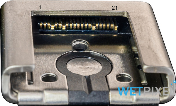
The state-of-the-art camera hot shoe interface has 4 to 24 pins. As an example, I will give the most complex one - a Sony hot shoe (Sony “Multi-Interface”), it has 24 contacts:
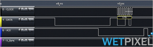
Information in the TTL protocol goes over several lines at the same time. For example, this is how the Nikon 4-line camera protocol looks like when viewed on a logic analyzer:
The camera initiates the communication protocol, recognizes the TTL compatible device on the hot shoe, and displays this with the “Flash” symbol in the service display. This icon confirms the compatibility of a particular camera and TTL system.
The variety and incompatibility of TTL protocols of cameras of different brands and the types of underwater strobes led to the need to develop special devices for automatic control of flash illuminators - the so-called TTL converters, which I have already mentioned above.
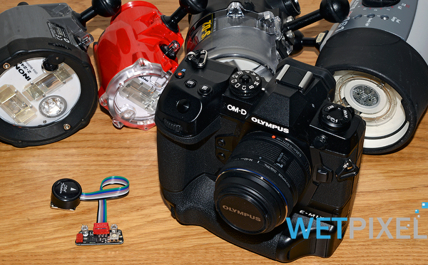
Under the UW Technics brand, TTL converters are now produced for most of the underwater housings on the market, compatible with Sony, Canon, Nikon, Olympus, Panasonic cameras.
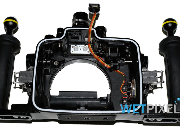
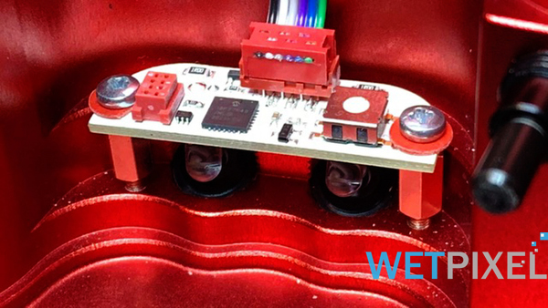
The photo below shows the latest TTL converter from UW Technics installed in the Isotta housing for the Olympus OM-D EM1 II. It supports TTL underwater flash control over optical and electrical cables, communicating via a hot shoe with the camera.
A TTL Converter for underwater photography is an electronic device with a microprocessor and built-in processing firmware that allows various TTL systems of different cameras to interact with multiple other underwater flash units. Well-known brands of underwater flash manufacturers supported include Inon, Sea & Sea, Ikelite, Subtronic, and Retra.
Each model of an underwater strobe differs in the parameters of the discharge tube (length, cross-section, shape, etc.) and control electronics. Therefore, the developers are forced to build and store various software TTL control profiles for these strobes in the memory (firmware) of the TTL Converter. Of course, the number of profiles must be limited. Therefore, as a rule, only 8-10 are used for the most popular strobe models. Users can select an appropriate profile via a miniature switch on the Converter board.
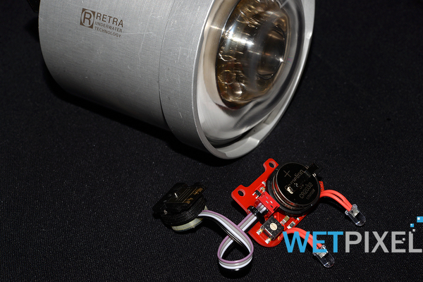
TTL Converters from UW Technics also support high-speed sync (HSS) with Retra strobes, shutter speeds up to 1/8000 sec are available.
The photo below shows the TTL Converter for Nauticam underwater housings for Sony A1-A9 cameras, supporting HSS synchronization with Retra strobes.
- Underwater Flash Exposure Fundamentals
- TTL Development History
- Digital TTL Primer
- High Speed Synchronization